
Active cooling of optical transceivers
Tier 1 OEM’s in telecom infrastructure market are designing the next standard for telecommunications, 5G. It will provide faster data transmission speeds than current LTE (4G) systems, approaching broadband speeds achieved with landlines.
The latency will be much lower, reducing the number of times packets need to be resent. This will be great for mobile users in densely populated areas trying to stream movies, music or live TV on their smart devices.
Faster data communications will present challenges for critical components such as optical transceivers. They are installed in radio units to transmit and receive data from the base station. The temperature of the device for outdoor environment will increase due to smaller form factors and no access to forced airflow, which will increase the heat flux density of the radio unit. This results in high temperatures that exceed the maximum operating limit of the optical transceiver, thus requiring an active cooling solution.
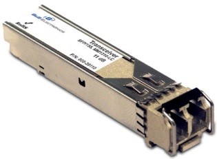
An optical transceiver is a Small Form Factor (SFP) pluggable transceiver as shown in Figure 1. The transceiver contains a laser diode that transmits data, and the ability to assure transmission of data depends on keeping the temperature typically below 70°C.
The traditional thermal solution for the SFP is currently passive, containing an interface material attached to a heat sink that dissipates heat through natural convection. This option, however, has been found to have difficulty with rejecting heat into ambient environment for radio units in 5G systems.
In natural convection, the heat transfer occurs from thermodynamic principal of heat moving from hot region to cooler region to find equilibrium or in this case from transceiver to heat sink to ambient air. Large surface areas are required to convect heat naturally, and unfortunately SFP form factors don’t allow for large heat sinks.
In forced convection, the heat transfer is assisted by forced airflow from fans and the heat transfer will improve with velocity of airflow. However, fans are not permitted due to the high maintenance costs with replacing them in the field. Many radio units are located in towers and are not easily accessible. Outdoor environments can be harsh, which will limit the operating lifetime of a fan versus indoor applications. Therefore, it is not expected that such a thermal solution will be cost effective for cooling of optical transceivers in outdoor environments.
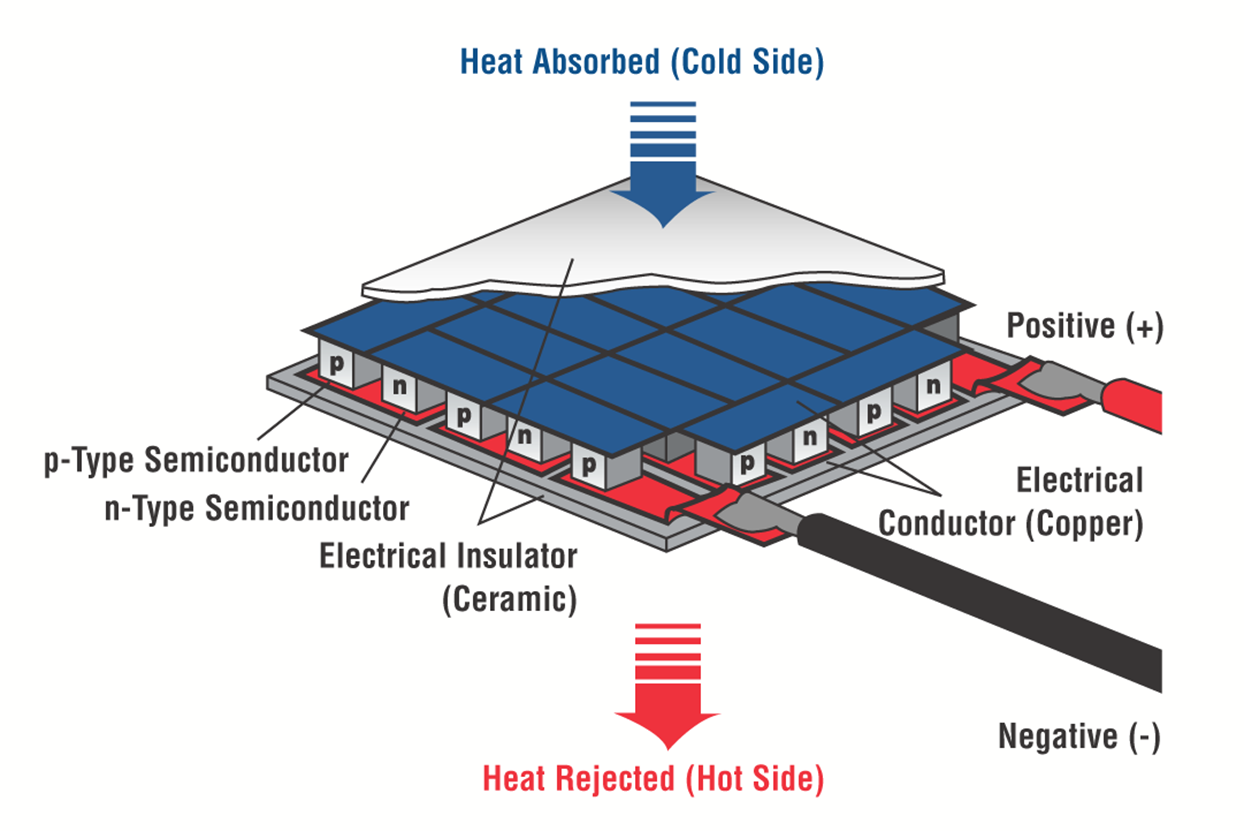
An active thermal solution that requires no maintenance and can cool hot spots below surrounding ambient conditions is Thermoelectric Modules, (TEMs). This is a semiconductor-based device made from BiTe that has unique properties to pass thru electric current while causing high thermal insulating characteristics.
As a result, a small heat pump is formed that removes heat from the control side to the hot side. It is commonly referred to as the Peltier effect. Ceramic substrates are used for heat spreading and electrical isolation to pass thru current on each P and N junction element. A TEM can be as small as 2x2mm, allowing it to operate in tight space constraints. Below is a schematic of a TEM.
Laird has developed a thermal solution using TEMs for optical transceivers. The key challenges were:
- Maintaining a high Coefficient of Performance (COP) to limit heat rejection requirements from TEM onto natural convective heat sink
- Durable construction to operate in elevated temperature environments, up to 120°C
- Develop a thermal solution with a high degree of reliability
The objective was to design a Thermoelectric Assembly (TEA) that would be capable of removing heat generated by optical transceiver running in an environment where temperatures can exceed 95°C.
Laird’s active cooling solution optimised the performance and efficiency by developing a custom TEA, as illustrated in Figure 3. Customisation down to the TE element allows for optimisation of heat pumping capacity to heat rejection mechanism for operating conditions with a ΔT of roughly ~30°C. The TEA is designed to accommodate specific footprints and input power constraints commonly available in the optical component market. Laird’s ATC (Active Transceiver Cooler) line of miniature form factor TEAs are designed to work with optical transceivers.
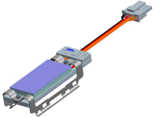
The TEM uses a high temperature solder construction. It is designed to accommodate the footprint of an EMI cage that goes around the optical transceiver. Laird interface materials are used to mount onto mating heat transfer surfaces and clips are used to assemble the ATC Cooler onto the EMI cage. An aluminium plate is used for structural integrity of the assembly and to aid in heat spreading. An NTC thermistor is adhered to the control side for temperature control.
To validate the functional performance of an ATC Cooler, Laird simulated a test setup, as shown in Figure 4, to test the system design under various conditions dependent on the heat load generated for a typical SFP, XFP or QSFP transceiver.
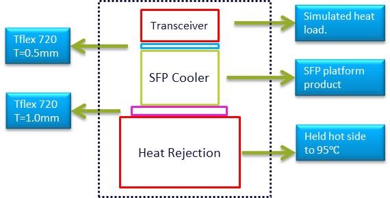
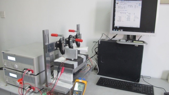
Figure 5 contains the test results. The hot side temperature of TEM was held to 95°C. This would simulate the temperature of hot side heat sink when TEM is turned off. The transceiver is powered to 4.5W, simulating the active heat source. The input power to TEM was gradually increased until the desired control temperature on optical transceiver was achieved. At an input power of 3.0W, the temperature of the optical transceiver reached a target temperature of 70°C. This temperature could be further reduced by increasing the power to the TEM.
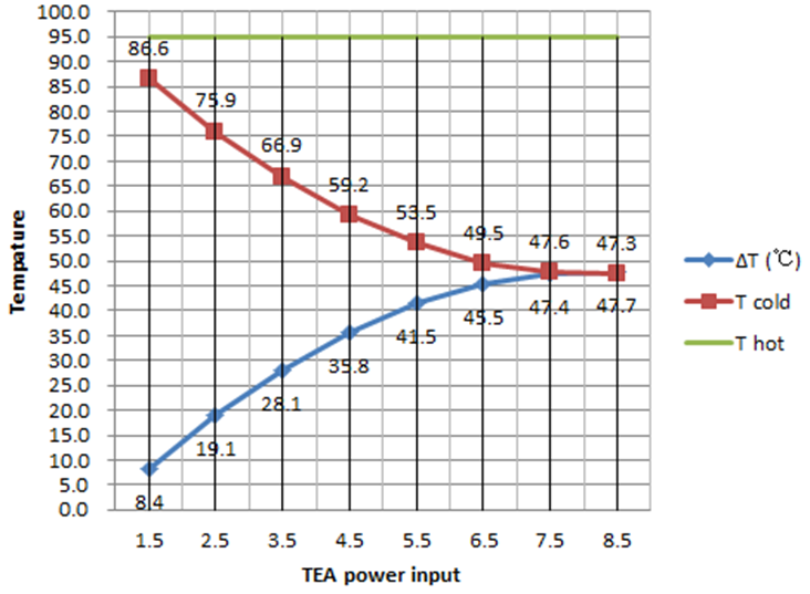
Figure 5. Measured XFP transceiver temperature as a function of TEM input power
This test was repeated using an ATC designed to cool a QSFP transceiver. The TEM configuration has been optimised to maximise COP. A typical active heat load for a QSFP transceiver is 7.5W. The input power to TEM was gradually increased until the desired control temperature on optical transceiver was achieved. At an input power of 4.5W, the temperature of the optical transceiver was reduced to a target temperature of 70°C. This temperature could be further reduced by increasing the power to the TEM as shown in Figure 6.
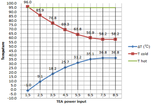
Figure 6. Measured QSFP transceiver temperature as a function of TEM input power
However, one note of caution needs to be mentioned - the hot side temperature of the TEM must also be considered. A poor heat dissipation mechanism can elevate hot side temperature and affect the control temperature achieved. Adequate heat sinking is required to keep the TEM operating as efficiently as possible. For alternate heat dissipation mechanisms’ a customised TEM maybe required to prevent thermal runaway.
The thermal solution for transceiver cooling in an outdoor environment yields an optimal solution to maintain form factor and minimise latency of a remote radio unit. Laird’s ATC line of miniature form factor thermoelectric assemblies provides the size and the cooling accuracy needed to obtain peak performance for SFPs under the more demanding data transmission requirements of upcoming 5G networks.
Product Spotlight
APV1111GVY
Panasonic

Panasonic PhotoMOS® Photovoltaic MOSFET High-Power Drivers
| SKU: | |
|---|---|
| Stock: | 3490 |
| Cost: | $3.95 |
