
Let there be better LED light
Thermal issues are the key technology barrier to LED adoption for general lighting applications. By Dr. John Parry, Electronics Industry Manager, Mechanical Analysis Division, Mentor Graphics.
As much as 95% of the electric input in traditional incandescent light sources becomes heat and is mostly dissipated by radiation. LEDs are much more efficient; 60% of the energy becomes heat and almost none of it dissipated through radiation. However, in order to keep the LEDs cool and promote quality light output, reliability and longer product life, heat must be efficiently removed by conduction and convection. The challenge for this rapidly growing industry is effective thermal management of solid-state lighting (SSL) products.
The LED lighting industry is hampered by a lack of standardisation on data relating to their thermal performance. Because LEDs emit a substantial proportion of the power they consume as light, the power emitted as light has to be taken into account when calculating their real thermal resistance. And because LED light emission and lifetime strongly depend on temperature, proper thermal characterisation of individual LED components is important. Accurate data for the real thermal resistance of LEDs is critical for lighting system designers to develop proper thermal management solutions of their SSL products. Knowledge about temperature dependence of the light output characteristics (such as luminous flux or colour coordinates) of LEDs is necessary for designing luminaires that provide light intensity and light distribution patterns required by lighting standards. Unfortunately, because of the lack of industry standards, LED vendors’ data sheets often do not provide sufficient useful information in this regard.
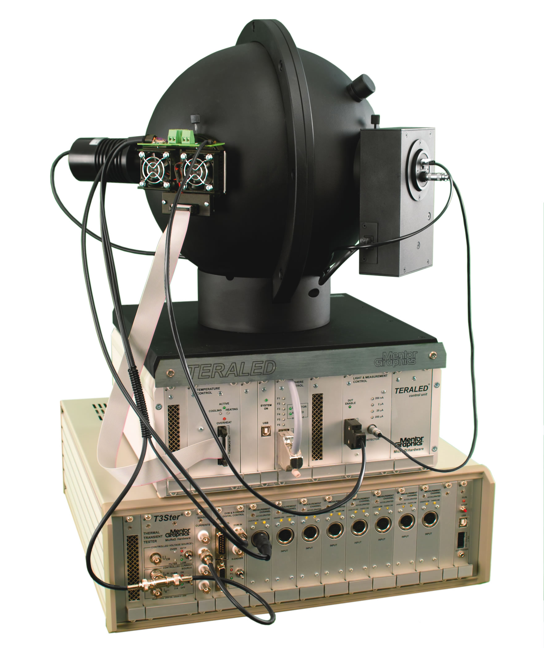
Figure 1: The TeraLED-T3Ster thermal characterisation and measurement system
With these factors and trends in mind, Mentor Graphics continues to create innovative solutions for the LED supply chain, from manufacturers through subassembly to end-user SSL products with the recent introduction of a larger TeraLED and an LED Module for the CAD-embedded CFD product, FloEFD. With these solutions, engineers can use combined thermal and radiometric measurements to accurately test their products for improved performance and reliability, and these results can be quickly and easily converted into compact models to use in computational fluid dynamics (CFD) for simulating not only the thermal behaviour, but also to predict light output properties of LEDs under different operating conditions, allowing SSL products to be designed and built using virtual prototyping techniques, avoiding the need for time-consuming and costly physical testing.
Better measurement
The market demand for bigger, brighter LEDs and light engines that dissipate more power has necessitated the development and release of a larger TeraLED sphere with greater heatsinking capability. The TeraLED tester now includes both 30 and 50cm integrating spheres and a range of cooling options to 50W. T3Ster measurement results can be converted into compact thermal models (CTMs) suitable for CFD simulation. These models have now been extended through TeraLED measurements to include temperature-dependent light output data. These provide SSL designers, for the first time, with the precise models of individual LEDs needed to calculate the hot lumens of their luminaire designs.
The first step using these systems is to measure the LEDs that are generally suitable for the lighting application and to evaluate them by thermal and radiometric characterisation. The LED must be measured as it transitions from a hot to a cold state of operation to be able to thermally characterise it using the so-called electrical test method. The results of such measurements are LED package thermal metrics and descriptive functions that will help design engineers understand the structure.
The proper thermal design of the cooling solution can be created when the latest JEDEC LED thermal testing standards are used in this approach to identify the real thermal resistance and the real thermal impedance of the LED package. Not only is the radiant power measured and used in the thermal resistance-impedance calculations, but the temperature dependence of other light output properties such as luminous flux or colour coordinates can also be measured. This way the best suitable LED from various LEDs of different vendors can be selected for the design of a particular lighting application. These LED testing standards are fully implemented by the T3Ster and TeraLED measurement systems. Figure 2 is an example of an LED junction temperature transient measured on a cold plate - as the JESD 51-51 and JESD 51-52 standards recommend.
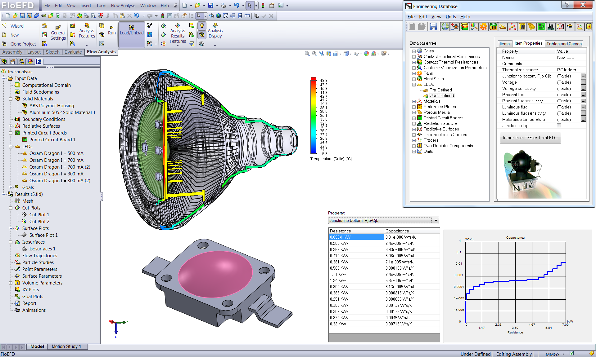
Figure 2: Typical LED Module interface illustrating the T3Ster-TeraLED workflow in FloEFD
The measured junction temperature transient is turned into thermal impedance if it is divided by the applied heating power. In the case of LEDs, this is the supplied electrical power (forward voltage x forward current) less the emitted optical power, also known as total radiant flux. The LED under test must be characterised optically to account for this. If the emitted optical power is not considered, the resulting thermal resistance will be smaller than reality, misleading the designers of the cooling solution. Measurement of the light output properties in combination with thermal tests as suggested, for example, by the JEDEC JESD 51-52 standard provides useful information about their temperature dependence.
The data processing software of the T3Ster system derives structure functions from the transient measurement, which are then converted into models that are accurate in the case of packages that possess one-dimensional heat-flow path such as power LED packages. Such models can be created as ‘side products’ when the junction-to-case thermal resistance (RthJC) of the package under test is identified according to the latest JEDEC transient measurement standard (JESD 51-14), based on the so-called transient dual interface method.
CFD for LEDs
The FloEFD LED Module allows designers to use accurate CTM and photometric models of LEDs obtained from T3Ster and TeraLED within a general purpose CFD simulation package (Figure 2). These models are uniquely driven at constant forward current as opposed to estimated power consumption inputs that yield less accurate predictions. This ensures correct accounting for power that is emitted as light when calculating the heat dissipation of the LED. As a result, the temperature, power consumption and light output in the application (hot lumens) of the LED are predicted accurately by simulation (Figure 3). In addition, thermally and photometrically characterised LED models (CREE XT-E; Osram Golden Dragon; Seoul P4; and Philips Luxeon REBEL) are provided. The module also includes the ability to account for adsorption of radiation in semi-transparent solids such as a lens in front of the LED and is able to represent a PCB as a compact model with orthotropic thermal conductivity.
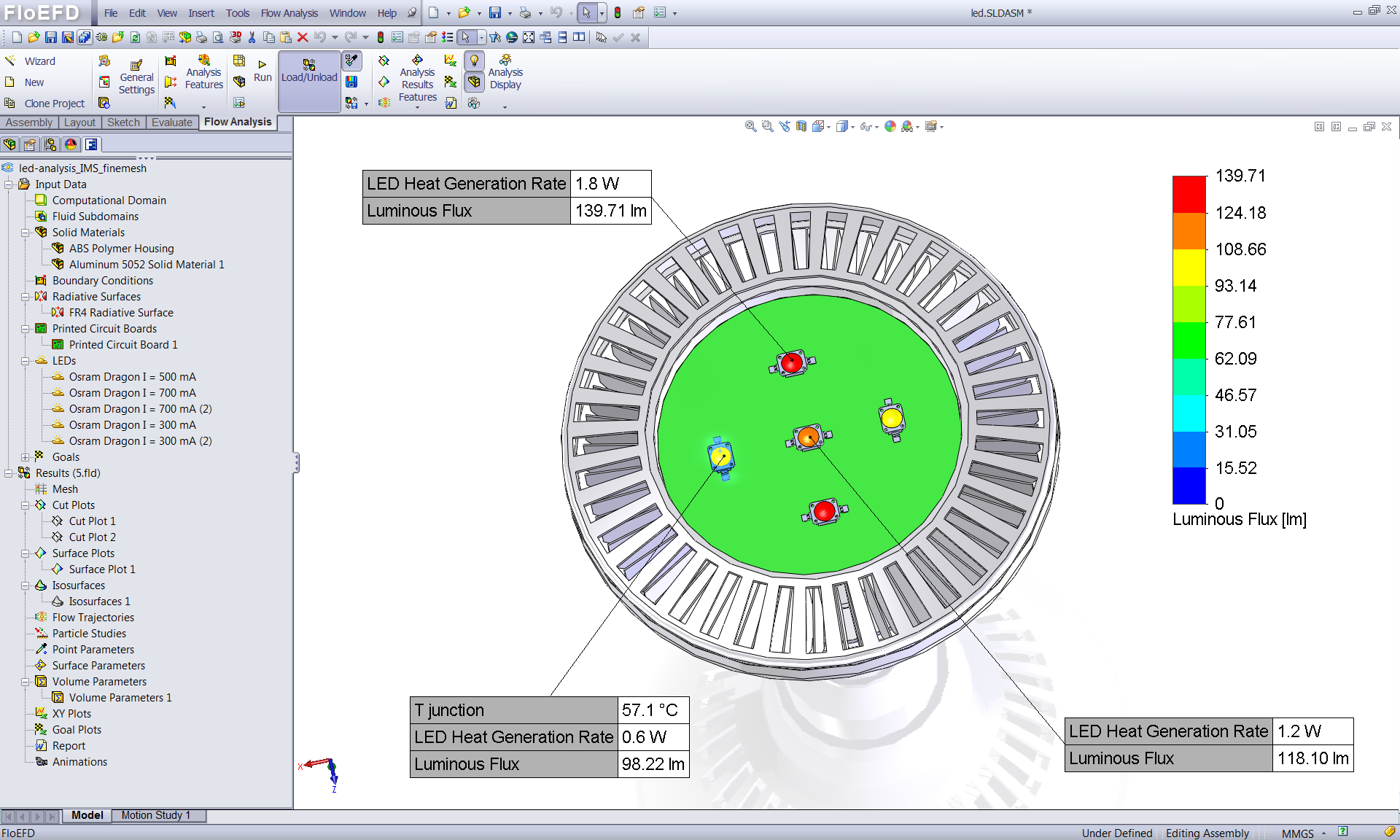
Figure 3: Typical LED Module hot lumens prediction for a retrofit SSL bulb
The LED Module provides the so-called JEDEC 2R thermal resistor model in an extended format. For the 2R model, the necessary information can be found easily in the datasheets. In case of LEDs, the junction-to-bottom resistor of the 2R model is relevant; it is more or less equal to the junction-to-case thermal resistance of the package. But for the junction-to-top resistance of the 2R model, the junction-to-lens thermal resistance is needed. This is usually not provided and it hardly can be correctly tested, and usually a sufficiently large value obtained from CFD simulations is provided. The way the standard 2R model is extended in FloEFD is that the junction-to-bottom part of the model is re-presented an RC model, which allows transient simulations because the thermal capacitance is also included in the model. However, the more detailed RC model requires more data of the LED, which often cannot be found in datasheets. In this case, FloEFD makes it easier with an interface to the thermal characterisation system.
Post-processing
A file can be exported out of T3Ster-Master thermal transient data post-processing software that can be read by FloEFD with all the necessary data for the RC model in form of a Cauer-type ladder model. This file contains not just single thermal resistance and capacitance from junction to bottom (Rjb and Cjb) values of the LEDs as a bulk value representing a single thermal time constant for the package, but represents the heat-flow path structure in details appropriate for accurate transient simulation using CFD analysis.
For the proper prediction of the LED’s hot lumens (luminous flux at operating junction temperature), an LED model in FloEFD also contains simple models for the radiant flux and luminous flux for constant drive currents of the LED. These models use the measured junction temperature sensitivity of these light output properties. Including the temperature sensitivity of these parameters is important to account for the complex, multi-domain operation of LEDs.
Over the last decade, as the efficiencies of LEDs has increased to the point where they are a viable replacement for incandescent bulbs and compact fluorescent lamps, the world has reached a tipping point in the usage of LED Lighting within automotive lighting, street lighting, back lighting (for consumer electronics), and now general lighting applications. With the new measurement, analysis, and simulation technology now available specifically for LEDs, product engineers can get better results because the component properties used in their application are based on real measured component data, which allows them to make better judgements for the thermal aspects of their design.
Author profile: A chemical engineer by training, John Parry earned a PhD in reactor design before getting involved with computational fluid dynamics more than 25 years ago. As Electronics Industry Manager for the Mechanical Analysis Division of Mentor Graphics, he has coordinated EC-funded projects and managed Knowledge Transfer Programs and strategic internal projects as well as overseeing the technical integration of MicReD’s business into the division. Dr. Parry serves on the JEDEC JC15 Thermal Standards Committee and on various conference committees and was General Chair of the SEMI-THERM 21 conference.
Product Spotlight
APV1111GVY
Panasonic

Panasonic PhotoMOS® Photovoltaic MOSFET High-Power Drivers
| SKU: | |
|---|---|
| Stock: | 3490 |
| Cost: | $3.95 |
