
Helping networks adopt optical interfaces
The demand for greater bandwidth is present in all applications but nowhere is this more apparent than in telecommunications and data communications infrastructures. The use of fibre optics is an effective way of adding bandwidth, but it comes with the requirement of a transceiver module to terminate each end of the cable.
By Eric Lan, Assistant Product Marketing Manager of Connect ASIC Product Line, Diodes
These transceivers must be placed close to the edge of the PCB in the equipment, and each transceiver needs to be controlled using a serial interface. As the number of channels increases so too does the number of control channels, and this can have a cumulative impact on the board space needed to support that.
By aggregating the serial control channels, developers can significantly reduce the number of discrete components required and the board space they subsequently need. These channel aggregators can also offer additional features, as this article will explore.
Optical transceivers pervade the network
The use of fibre communications is increasing throughout the network infrastructure, all the way to the edge. Fibre to the home offers higher bandwidth broadband services to consumers and businesses, but that bandwidth needs to be supported all the way back to the server or data centre to be viable at a guaranteed service level.
As well as bandwidth, there are a number of reasons why fibre is attractive from a technical point of view. It suffers from much less attenuation than copper cable across a wide frequency band. It is generally much lighter than copper, and smaller in diameter, meaning operators can support more connections for a given space, size or weight. Fibre is also much more secure than cable, physically, and safer, electrically. In addition and, perhaps most pertinently, fibre is effectively immune from the effects of all forms of electromagnetic energy.
Transceivers are the interface between high speed optical communications and the rest of a network. They comprise optical subassemblies for transmission and reception, which convert digital information to and from a light wave, in the form of a pulsed laser. This is achieved using a photoemitter or photoreceiver along with an arrangement of lenses. Here, the known issues that fibre avoids so well, such as EMI, can be reintroduced and so it is common to use differential signalling on the digital side.
Today, fibre coexists with Ethernet running over copper to interconnect equipment and join networks together (including local area, metro area and storage area), using network interface cards, switches and routers. Each channel needs to be terminated using an optical transceiver, and each transceiver needs to be controlled. While optical fibre delivers significant benefits in network capacity, the management of transceivers is causing an expansion of components at the PCB level.
Aggregating control
It may seem like more bandwidth is always the answer but, in reality, networks feature various speeds, with some channels being aggregated to deliver the very highest bandwidth. This results in multiple transceivers across a network and even within a switch or router, each one of which is optimised for a particular type of connection, but all of which need to be managed.
This task has evolved over time and often the simplest solution to managing a growing network is to put in a dedicated control path for each channel. This may work but at some point the FPGA or ASIC being used to manage the transceivers becomes pin-limited, or the size of the PCB needs to be increased (Figure 1).
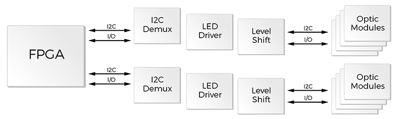
Figure 1: A typical approach to controlling optical modules
It is apparent that adding more components to expand a network interface becomes problematic, both in terms of the physical space required and the system power it takes. The more sustainable solution is to replace the multiple intermediary devices (I2C demultiplexer, LED driver and level shifter) with a single device capable of controlling multiple modules (Figure 2).
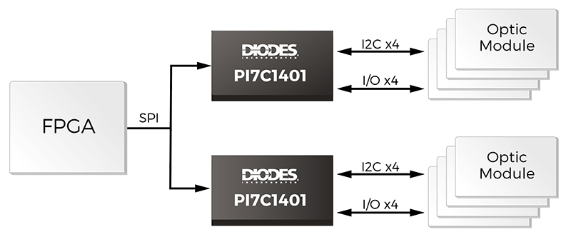
Figure 2: Aggregating control of multiple optical modules
An example of this is the PI7C1401 quad port expander from Diodes Incorporated. Each device provides aggregation of up to four I2C or SPI interfaces, which allows a single device such as an FPGA or ASIC to address and control a minimum of four optical modules with a single I2C/SPI interface, instead of dedicating a port to each (Figure 3).
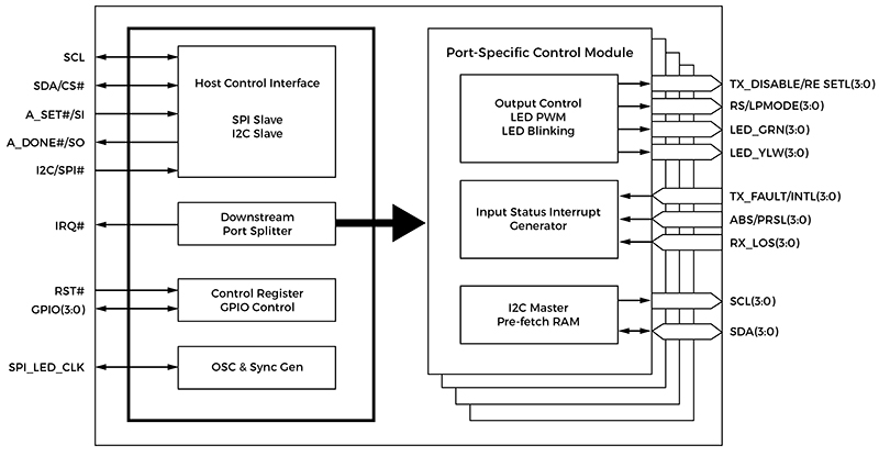
Figure 3: A functional block diagram of the PI7C1401 Port Expander
An obvious benefit of using such a device is its 1:4 demultiplexing capabilities, which can easily expand to 1:56 when using up to 14 PI7C1401 devices configured in a chain with their input wire-or’d together. An auto-addressing scheme is used, so individual devices do not need a unique address.
This gives an immediate increase in capacity and, where space allows, enables extra optical modules to be fitted and controlled in an existing design. As the host device – often an FPGA, microprocessor or ASIC – will typically operate at a high processing frequency, it will be more than capable of managing multiple, relatively low-speed ports from a single interface. In the vast majority of cases the limitation on capacity would be pin count, rather than processing speed, which directly supports the practice of multiplexing multiple control ports through a single interface.
Secondary advantages are also available in the case of the PI7C1401, which offers extended features that go beyond simple demultiplexing and cross over into module management. This allows many of the control functions to be offloaded onto the port expander, thereby freeing up the host device to focus on other activities. This may even allow the host device to be cost-optimised by lowering the I/O pin count or processing capability. It will also reduce the routing layer congestion at the host.
The speed of the host interface is selectable and dependent on the protocol being used; an I2C interface can operate at up to 1MHz and when configured as a SPI interface it can operate at up to 33MHz. The PI7C1401 also features GPIO pins that can be used for management functions, controlled by registers.
Each channel has two outputs dedicated to driving status LEDs; most SFP+ and QSFP+ modules will use a yellow and green LED per port to indicate the status of the link (link up, link down etc). The internal circuit is controlled using configuration registers, which include the LED Mode, ON Time, OFF Time and Brightness control registers.
As some low-speed interface specifications, including SFF-8472 and SFF-8431, define logical device addresses, the PI7C1401 is able to use the address mapping scheme to enable the upstream host to issue downstream read or write operations, referred to as direct accesses.
In addition, the port expander can also perform pre-fetch read operations from downstream modules. This data is stored in the PI7C1401’s on-chip 32byte FIFO. The size and address of the data is configurable, and the pre-fetch operation can be scheduled or triggered by an interrupt. Direct accesses have a higher priority than a pre-fetch operation.
The management features of the PI7C1401 provide an effective and valuable addition to the port expansion functionality, which can directly improve a system’s performance.
Conclusion
The move to optical interfaces is increasing at every point in the network topology, thanks to the benefits they bring. Managing this expansion requires dedicated control channels, which can rapidly consume physical resources.
The use of a port expander addresses the challenge of adding more control channels using existing resources, while also providing an effective method for offloading many of the port management tasks. By raising the level of abstraction, the host device is able to better manage routing layer tasks and deliver greater overall system efficiency.
Product Spotlight
APV1111GVY
Panasonic

Panasonic PhotoMOS® Photovoltaic MOSFET High-Power Drivers
| SKU: | |
|---|---|
| Stock: | 3490 |
| Cost: | $3.95 |
