
New VDE digital isolation standard is a game-changer
For more than two decades, a standard for optocouplers has proven isolation in almost all applications and equipment that demand secure separation of electrical circuits from high-voltage events. The baseline was the German VDE 0884 standard, finalised in 1987, and the international standard IEC 60747-5, which followed soon after. By Werner Berns and Kannan Soundarapandian, Texas Instruments.
The standard has been revised and improved over the years, with the IEC 60747-5-5 (VDE 0884-5) published in 2013. This standard is considered one of the most successful component standards worldwide giving system engineers confidence in designing circuits with insulation capability.
About 10 years ago, newer methods to create reliable galvanic isolation were developed, reaching higher data rates and isolated power transfer. Now capacitive- and later magnetic-coupled circuits could be integrated into a chip package, significantly extending electrical speed and timing performance of digital isolators.
Besides the technical difficulties and challenges of the newer technology in the early days, a key unresolved need has persisted, even as magnetic and capacitive couplers have become a large and growing share of the market: a worldwide standard for magnetic and capacitive couplers.
Magnetic and capacitive couplers standard
In 2006 the DKE (VDE Association for Electrical, Electronic & Information Technologies) delivered a dedicated standard for magnetic and capacitive couplers (VDE 0884-10). In 2011, an international equivalent standard (IEC 60747-17) was attempted, but failed when critical mass in participation (four experts from four countries) was not achieved.
In the summer of 2014, the German second edition of VDE 0884-10 was finalised. It includes significant improvements over the previous revision and the current optocoupler standard. Recently, this second edition was submitted to the IEC as a proposal for a new work item to be accepted, with enough experts nominated, during the general IEC meeting in November 2014.
Capacitive isolator certification
The lack of a dedicated standard for magnetic and capacitive couplers forced the industry to certify those products to the existing optocoupler standard (IEC 60747-5-5, or its predecessor IEC 60747-5-2) for almost a decade. Some test and certification labs accepted certifying magnetic and capacitive couplers on an exception basis to the above mentioned optocoupler standard by subjecting material to the same tests as the optocouplers.
In May 2014, this practice was withdrawn by the DKE and, therefore, no longer a certification option at the VDE test and certification lab. Furthermore, all existing certifications for magnetic and capacitive couplers issued based on IEC 60747-5-5 will be reissued based on VDE 0884-10 Ed.1, the published German magnetic and capacitive isolation standard, and later based on Ed.2 (expected in December 2014). Other test and certification labs, especially outside of Germany, might be willing to continue to certify against the optocoupler norm, as the DKE decision is not binding to them. Nevertheless, the new VDE 0844-10 Ed.2 is a much stronger norm than the optocoupler norm, so there is little need to continue using the optocoupler standard.
VDE 0884-10 Ed.2 versus IEC 60747-5-5
There is little difference between these two standards. But improvements made to the VDE 0084-10 Ed.2 set an unprecedented new level of rigour in component standards (see Table 1). The working voltage is a key parameter on which engineers focus first to see the isolation performance of a coupler when high-voltage is applied across the isolation barrier over the product lifetime.
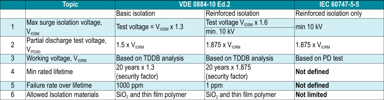
Table 1 - Main differences between the optocoupler and magnetic/capacitive coupler standards
Optocouplers use the Partial Discharge (PD) test to determine the maximum working voltage (VIORM). This test lasts for one second in production and qualification of the device. Testing for VIORM is also performed for magnetic and capacitive couplers. However, a more modern method is used by taking the working voltage determined from a Time-Dependent Dielectric Breakdown (TDDB) analysis.
The TDDB analysis is a well-known methodology to learn about lifetime at accelerated stress test conditions. In automotive systems, for example, the acceleration is temperature to get lifetime estimations of product reliability at high-temperature operation. In the case of capacitive and magnetic isolators, the test voltage is accelerated to increased levels such as 5, 6, 7kV, and so on. Depending on the test voltage, it takes days, weeks, months and longer to force a breakdown of the isolation barrier. According to VDE 0884-10 Ed.2, at least one data point must exceed 10e7 seconds (116 days) before failure. Furthermore, the tests and test voltage have to be chosen for worst case conditions (temperature, waveform).
Based on the resulting Weibull chart, we get data points (X1, X2 … Xn) for a given failure rate (Table 1, row 5 for ppm rates). The resulting dependency for lifetime over stress voltage can be drawn (see Figure 1). For SiO2 (silicon dioxide), the result is a linear curve. For thin film polymer, the result is a 1/V curve. At the point where the curve crosses the required lifetime (37.5 years for reinforced level – new mandate in latest VDE0884-10 Ed.2), we can draw a line down to the voltage scale to get the stress voltage for this lifetime point. This voltage is then divided by 1.2 (extrapolation factor for margin), which results in the working voltage, VIORM.
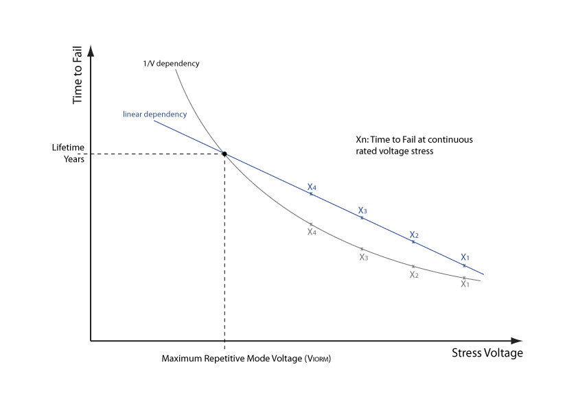
Figure 1 - Determining the working voltage from TDDB lifetime analysis
This procedure delivers a scientifically rigorous lifetime estimation of 37.5 years. The dependency of lifetime versus stress voltage is evident. It enables an accurate estimate of the maximum working voltage for a longer or shorter lifetime. This shows very high transparency and delivers high valued information directly into the hands of engineers who want to know more than just a working voltage value. In the case of the optocoupler standard, there is no lifetime estimation requirement outside of the partial discharge test.

Product Spotlight
APV1111GVY
Panasonic

Panasonic PhotoMOS® Photovoltaic MOSFET High-Power Drivers
| SKU: | |
|---|---|
| Stock: | 3490 |
| Cost: | $3.95 |
